Colpitt Oscillator Calculator
This CalcTown calculator calculates the resonant frequency of a Colpitt Oscillator Circuit.
The Colpitt’s oscillator is designed for generation of high frequency
sinusoidal oscillations (radio frequencies ranging from 10KHz to 100MHz). They are
widely used in commercial signal generators up to 100MHz. Colpitt's oscillator is same
as Hartley oscillator except for one difference. Instead of using a tapped inductance,
Colpitt's oscillator uses a tapped capacitance.
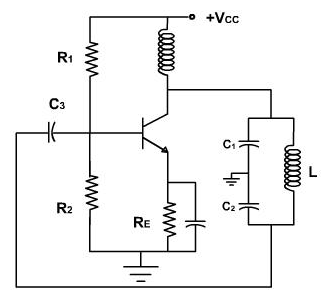
The circuit diagram of Colpitt’s oscillator using BJT is shown in Fig. It consists
of an R-C coupled amplifier using an n-p-n transistor in CE configuration. R1 and R2 are
two resistors which form a voltage divider bias to the transistor. A resistor RE is
connected in the circuit which stabilizes the circuit against temperature variations. A
capacitor CE is connected in parallel with RE, acts as a bypass capacitor and provides a
low reactive path to the amplified ac signal. The coupling capacitor CC blocks dc and
provides an ac path from the collector to the tank circuit.
The feedback network (tank circuit) consists of two capacitors C1 and C2 (in
series) which placed across a common inductor L. The centre of the two capacitors is
tapped (grounded). The feedback network (C1, C2 and L) determines the frequency of oscillation of the oscillator. The two series capacitors C1, and C2 form the potential
divider led for providing the feedback voltage. The voltage developed across the
capacitor C2 provides regenerative feedback which is essential for sustained oscillations.
Colpitt Oscillator Calculator
Click here to view image
Where,
L = coupled inductor
C1 = coupled capacitor 1
C2 = coupled capacitor 2
C = Equivalent capacitance of the coupled capacitors
f0 = resonant frequency
When the collector supply voltage Vcc is switched on, collector current starts
rising and charges the capacitors C1 and C2. When these capacitors are fully charged, they
discharge through coil L setting up damped harmonic oscillations in the tank circuit. The
oscillatory current in the tank circuit produces an a.c. voltages across C1, C2. The
oscillations across C2 are applied to base-emitter junction of the transistor and appears in
the amplified form in the collector circuit and overcomes the losses occurring in the tank
circuit.
The feedback voltage ( across the capacitor C2) is 180° out of phase with the
output voltage ( across the capacitor C1), as the centre of the two capacitors is
grounded. A phase shift of 180° is produced by the feedback network and a further phase
shift of 180° between the output and input voltage is produced by the CE transistor.
Hence, the total phase shift is 360° or 0°, which is essential for sustained oscillations, as
per, the Barkhausen criterion. So we get continuous undamped oscillations.