Hartley Oscillator Calculator
This CalcTown calculator calculates the resonant frequency of a Hartley Oscillator Circuit.
The Hartley oscillator is designed for generation of sinusoidal
oscillations in the R.F range (20 KHz - 30 MHz). It is very popular and used in radio
receivers as a local oscillator.
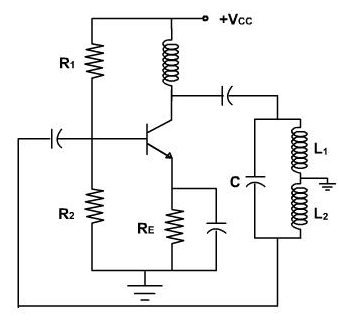
The circuit diagram of Hartley oscillator (parallel or shunt-fed) using BJT is
shown in Figure. It consists of an R-C coupled amplifier using an n-p-n transistor in CE
configuration. R1 and R2 are two resistors which form a voltage divider bias to the
transistor. A resistor RE is connected in the circuit which stabilizes the circuit against
temperature variations. A capacitor CE is connected in parallel with RE, acts as a bypass
capacitor and provides a low reactive path to the amplified ac signal. The coupling
capacitor CC blocks dc and provides an ac path from the collector to the tank circuit. The
L-C feedback network (tank circuit) consists of two inductors L1, and L2 (in series) which
are placed across a common capacitor C and the centre of the two inductors is tapped as
shown in fig. The feedback network (L1, L2 and C) determines the frequency of
oscillation of the oscillator.
Hartley Oscillator Calculator
Click here to view image
Where,
C = coupled capacitor
L1 = coupled inductor 1
L2 = coupled inductor 2
M = mutual inductance between the two inductors
L = Equivalent capacitance of the coupled capacitors
f0 = resonant frequency
When the collector supply voltage Vcc is switched on, collector current starts
rising and charges the capacitor C. When this capacitor is fully charged, it discharges
through coils L1 and L2, setting up damped harmonic oscillations in the tank circuit. The
oscillatory current in the tank circuit produces an a.c. voltage across L1 which is applied
to the base emitter junction of the transistor and appears in the amplified form in the
collector circuit. Feedback of energy from output (collector emitter circuit) to input
(base-emitter circuit is) accomplished through auto transformer action. The output of the
amplifier is applied across the inductor L1, and the voltage across L2 forms the feedback
voltage. The coil L1, is inductively coupled to coil L2, and the combination acts as an
auto-transformer. This energy supplied to the tank circuit overcomes the losses occurring
in it. Consequently the oscillations are sustained in the circuit.
The energy supplied to the tank circuit is in phase with the generated oscillations.
The phase difference between the voltages across L1 and that across L2 is always 180°
because the centre of the two is grounded. A further phase of 180° is introduced between
the input and output voltages by the transistor itself. Thus the total phase shift becomes
3600
(or zero), thereby making the feedback positive or regenerative which is essential
for oscillations. So continuous undamped oscillations are obtained.