Narrow Band-pass Filter Calculator
This CalcTown calculator calculates the center frequency, quality factor and bandwidth of a narrow band-pass filter.
The multiple feedback bandpass filter has a simple design, but it is difficult to calculate the values for a given set of parameters. These filters are useful for equalization, analysis and other tasks such as the Sound to Light converter, vocoder, etc.
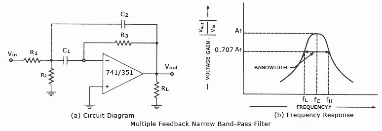
This type of active band pass design produces a “tuned” circuit based around a negative feedback active filter through resistor R3 and capacitor C2 giving it a high Q-factor (up to 25) amplitude response and steep roll-off on either side of its center frequency. Because the frequency response of the circuit is similar to a resonance circuit, this center frequency is referred to as the resonant frequency, ƒr.
Narrow Band-pass Filter Calculator
Click here to view image
Where,
C1,C2 (C) = Capacitors
R1, R2, R3 = Resistors
Q = Quality Factor of the filter
BW = Bandwith of the filter
fc = center frequency of the filter
Resonant Frequency Point
The actual shape of the frequency response curve for any passive or active band pass filter will depend upon the characteristics of the filter circuit with the curve above being defined as an “ideal” band pass response. An active band pass filter is a 2nd Order type filter because it has “two” reactive components (two capacitors) within its circuit design.
As a result of these two reactive components, the filter will have a peak response or Resonant Frequency ( ƒr ) at its “center frequency”, ƒc. The center frequency is generally calculated as being the geometric mean of the two -3dB frequencies between the upper and the lower cut-off points.
The “Q” or Quality Factor
In a Band Pass Filter circuit, the overall width of the actual pass band between the upper and lower -3dB corner points of the filter determines the Quality Factor or Q-point of the circuit. This Q Factor is a measure of how “Selective” or “Un-selective” the band pass filter is towards a given spread of frequencies. The lower the value of the Q factor the wider is the bandwidth of the filter and consequently the higher the Q factor the narrower and more “selective” is the filter.