Wilkinson Power Divider Calculator
This CalcTown calculator calculates the parameters related to Wilkinson's power-divider circuit.
In the field of microwave engineering and circuit design, the Wilkinson Power Divider is a specific class of power divider circuit that can achieve isolation between the output ports while maintaining a matched condition on all ports. The Wilkinson design can also be used as a power combiner because it is made up of passive components and hence reciprocal. First published by Ernest J. Wilkinson in 1960, this circuit finds wide use in radio frequency communication systems utilizing multiple channels since the high degree of isolation between the output ports prevents cross-talk between the individual channels.
It uses quarter wave transformers, which can be easily fabricated as quarter wave lines on printed circuit boards. It is also possible to use other forms of transmission line (e.g. coaxial cable) or lumped circuit elements (inductors and capacitors).
It splits an input signal into two equal phase output signals, or combines two equal-phase signal into one in the opposite direction. Wilkinson relied on quarter-wave transformers to match the split ports to the common port.
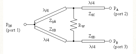
Click here to view image
Where,
PA = Power output of Port 2
PB = Power output of Port 3
Z0 = Characteristic Impedance of the overall system
Rw = Terminating resistance between two output ports.
Z0A, Z0B, Z0C, Z0D = Branch impedances
Network theorem governs that a divider cannot satisfy all three conditions (being matched, reciprocal and loss-less) at the same time. Wilkinson divider satisfies the first two (matched and reciprocal), and cannot satisfy the last one (being loss-less). Hence, there is some loss occurring in the network.
No loss occurs when the signals at ports 2 and 3 are in phase and have equal magnitude.
However, some modification can be done to achieve unequal power division at the output ports. By cascading, the input power might be divided to any n-number of outputs.
Advantages:
- Simplicity: The Wilkinson divider / splitter / combiner is particularly simple and can easily be realised using printed components on a printed circuit board. It is also possible to use lumped inductor and capacitor elements, but this complicates the overall design.
- Cost: When the Wilkinson power divider is realised using printed circuit board elements, the cost is very low - possibly the only increase above that of the single resistor used results from an increase in the board area used as a result of the printed elements. However to reduce losses, a low loss PCB substrate may need to be used and this would increase the cost.
- Loss: If perfect components were used, the Wilkinson splitter divider would not introduce any additional loss above that arising from the division of the power between the different ports. In addition to this, the real components used for the Wilkinson splitter can be very low loss, especially when PCB transmission lines are used along with low loss PCB substrate material.
- Isolation: The Wilkinson divider / combiner provides a high degree of isolation between the "output" ports.
Disadvantages:
- Frequency response: As the Wilkinson splitter is based around the use of quarter wave transmission lines, it has a limited bandwidth, although there are some Wilkinson splitters available that offer reasonably wide bandwidths.