Zener Diode circuit design Calculator
This CalcTown calculator calculates the Input Resistance (Ri) in a Zener Diode voltage regulator circuit so that the designed specifications of input voltage and load resistance can be met.
*Please note that it has been assumed that the minimum Zener Current is 10% of the maximum Zener Current. Although in more practical applications, it is usually 20-30%.
**Out of the two resistance values shown in the output, please choose the one with lower magnitude and neglect the higher value.
Zener Diode circuit design Calculator
Click here to view image
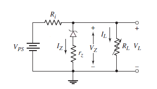
where
VPS = Voltage of the Power Source
IL = Current Flowing through the Load Resistance
IZ = Current Flowing through the Zener Diode
VZ = Zener Voltage
IZ(max)= Maximum Zener Current
and Load Resistance and Power Source Voltage are variable over a certain range.